|
||
 |
| Home |
| Who Is Stone Marmot? |
| Hear Our Music |
| Read Our Lyrics |
| Buy Our Music and Merchandise |
| News |
| Rants and Raves |
| Contact Us |
|
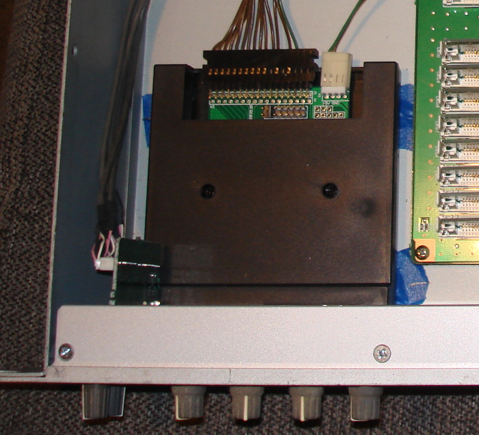
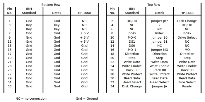
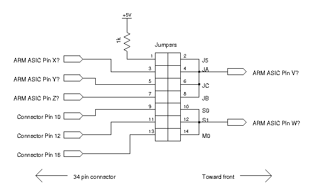
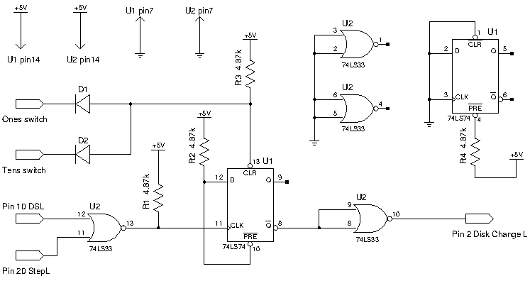
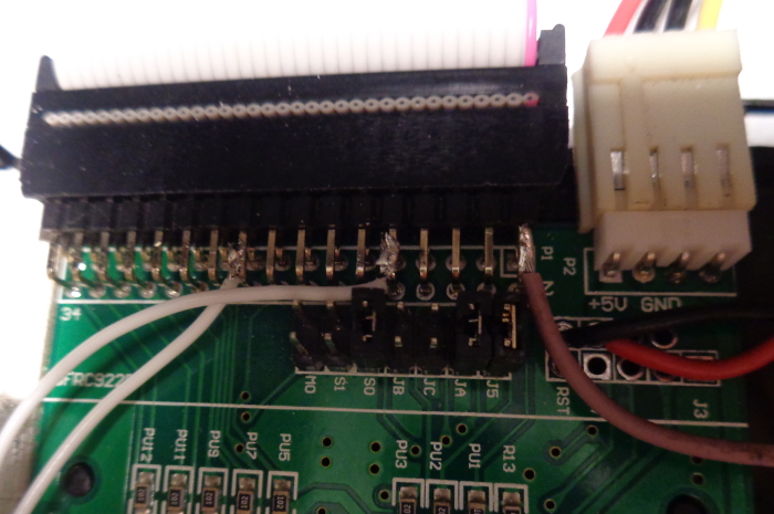
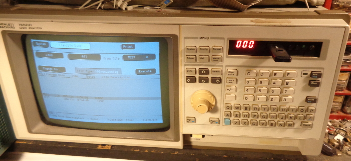
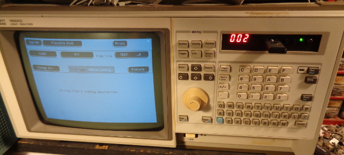
Gotek Floppy Drive Emulator In HP Logic Analyzer By Sid of Stone Marmot Oct. 20, 2020 The floppy drives used in many electronic devices in the 1980's and 1990's are now frequently failing and the disks themselves are failing. Many of these electronics devices are still otherwise working and quite useful. So many of us are looking for alternatives to these floppy drives that will keep these devices still functioning. Floppy drive emulators are a potential replacement. These devices usually have the same form factor as standard floppy drives and use the same cables and interface as the floppy drive. The data is usually stored on either a compact flash card or a USB thumb drive in these emulators. Gotek makes one of the most popular and cheapest of these floppy drive emulators. Its data is stored on a USB thumb drive. I have three of these devices. All are the same model, even though they were purchased up to six years apart from different vendors. I think the model number is SFR1M44-U100K-R. If you press and hold both front panel buttons at the same time during power up, the code displayed on the three character front panel display is "U01 126 F01" for all three emulators. So everything I say in this essay refers to this model and may not be 100% applicable to other Gotek models. One of these emulators is in a Korg Triton Rack music synthesizer, as shown in Figure 1. Another is in a Dell Optiplex GX280 tower computer, though it has been installed and worked in other tower computers. Both of these emulators were plug and play, working after simply plugging in the appropriate connectors with no changes in the jumpers on the emulators from how they were received from the vendors. The third emulator is installed in an HP 1660C logic analyzer. It was not plug and play. First, the HP1660C had no four pin floppy drive power connector. So that indicated that power was somehow coming through the 34 pin floppy drive interface connector. Figure 2 shows the signal definition for the IBM standard (the most common), Gotek, and the HP 1660C 34 pin floppy drive interface cables. I found the HP 1660C floppy drive interface definition in the 1660C series service manual. The only differences that matter in what I'm calling the bottom row of connector pins are in pins 7, 9 and 11, which are GND (ground) for the IBM standard and the Gotek but + 5 V for the HP 1660C. The simple solution is to cut these lines in the ribbon cable between the HP 1660C and the Gotek, as shown in Figure 3. Note that in the final assembly this section of the cable is covered with tape to keep these cut lines from shorting to anything. 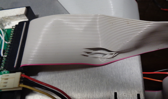 Figure 3 - Floppy drive signal cable with lines 7, 9, and 11 cut. I then soldered part of a power supply harness I salvaged from a tower computer that had both a floppy drive power connector and a standard parallel hard drive connector in place of the hard drive connector that was already present in the HP 1660C. Note that a typical power supply harness from an IBM PC compatible computer has black wires for ground, red wires for + 5 V, and yellow wires for + 12 V, whereas my HP 1660C has black wires for ground, an orange wire for + 5 V, and a red wire for + 12 V. So check your voltages before and after you wire your harness so you don't get the 5 and 12 V wires crossed. Over half of the signals in the top row are the same for the three connector definitions. But there are some differences. Fortunately, most of the differences appear to be programmable with jumpers for the Gotek. I could not find a good jumper definition or anyone who had buzzed out the jumper wiring for the Gotek, so I buzzed it out. Figure 4 shows my interpretation of the results. It appears that the pins closest to the front of the emulator for the jumper positions labeled S0, S1, and MO are all tied together and go to a pin on the ARM STM32F105 microcontroller, henceforth referred to as the ARM. I call this pin ARM ASIC Pin W. I didn't buzz out which specific pins on the ARM any of these signals go to, as I didn't want to risk damaging the ARM and it would do me no good anyway, since I have no way or desire to reprogram the firmware in the ARM. This signal apparently tells the ARM the device is selected, so it needs to be jumpered to a device select signal coming into the emulator. This would be connector pin 12, DS1, for most devices following the IBM standard floppy drive definition. That is why most of these emulators are shipped with a jumper in the S1 position, between the pins I labeled as 11 and 12 on the jumper header, as you can barely see in Figure 1. But the drive select signal is on pin 10 of the 34 pin connector for the HP 1660C, so this jumper must be moved to the S0 position, shorting pins 9 and 10 on the jumper header. Some people put more than one jumper in these S0, S1, and MO positions. This probably won't damage anything electrically as all the signals to and from the floppy drive are open collector. But you may get some odd behavior if more than one of these signals tries driving this ASIC pin W, so I don't recommend more than one jumper in these positions unless Gotek specifically recommends it for your host device. It appears that the pins closest to the front of the emulator for the jumper positions labeled J5, JA, JC, and JB (jumper header pins 2, 4, 6, and 8) are all tied together and go to a pin on the ARM I call ARM ASIC Pin V. Jumper header pin 1 appears to go to a 1 kOhm pullup resistor to + 5 V. The other three jumper header pins 3, 5, and 7 go to other ARM ASIC pins I call X, Y, and Z, respectively. I don't know what any of these ARM ASIC pins are specifically. Other Gotek literature show anywhere from zero to four jumpers in these positions, depending upon the host device the emulator is going into, so it must be safe to put any number of jumpers in these four positions. Incidentally, two of my emulators came with a jumper between header pins 2 and 4. This obviously does nothing as it just shorts together two pins that are already shorted together in the Gotek printed circuit board. Apparently, this jumper is just a spare that this particular vendor was kind enough to include in case I need it. One Gotek document I have states that a jumper in the JA position (shorting jumper header pins 3 and 4) switches pin 34 on the 34 pin floppy drive connector from being a "Disk Change" signal to a "Ready" signal. My tests confirm this for my emulators. I found that adding a jumper in the J5 position (shorting jumper header pins 1 and 2) while keeping the jumper in the JA position allowed my emulator to fully function in my HP 1660C logic analyzer except that it wouldn't recognize disk changes. Some other jumper combinations also worked but with much slower operation and again it wouldn't recognize disk changes. No jumper combination would recognize disk changes when in the HP 1660C. Also, a jumper in the JB position would cause connector pin 2 to go high briefly at power up and then go and stay low until the next power cycle. Connector pin 2 stays high if there is no jumper in the JB position. Since this signal is open collector, we want pin 2 high so we can control it, so no jumper in the JB position. So I determined I need to have jumpers in the S0, JA, and J5 positions only for best operation of my emulator in the HP 1660C. But I also need to somehow generate a disk change signal on pin 2 of the 34 pin connector. Research showed that most floppy drives with a "Disk Change" signal on pin 2 and a "Ready" signal on pin 34 expect timing for the "Disk Change" as shown in Figure 5. Ideally, you would just change the firmware in the ARM to generate a "Disk Change" signal with this timing. Since I am unfamiliar with the STM32F105 microcontroller and can't see any need to use this device in the future, I don't have any of the support software and hardware for this device and it would take me too long and cost too much to justify trying to update the firmware for this one use. There may also already be a version of the Gotek firmware out there somewhere that already does this, but I haven't found it. Figure 6 shows the circuit I came up with to generate a "Disk Change" signal with the timing shown in Figure 5 using parts I already had in my parts stock. Since pin 2 must be driven by an open collector driver, U2 must be an open collector device. The cathodes of D1 and D2 tie to the high side of the tens and ones switches on the Gotek front panel. The other side of each of these switches is already connected to ground on the Gotek board. The resistor values aren't critical as anything between 1 k and 25 k will probably work, though something between 4 k and 6 k is probably optimum. I just had a bunch of 4.87 k resistors in my parts stock. I didn't show the bypass caps but I'm using a 10 nF ceramic cap on each IC and a 100 uF, 16 V polarized cap for the board. I'm not going into a lot of detail here as I'm assuming anyone who can justify buying a logic analyzer and knows how to use it is already pretty advance in their electronics skills. You can probably come up with better ways to do this with parts you already have and are more familiar with. Adding this circuit shown in Figure 6 made the emulator 100 % functional in my HP1660C, including recognizing disk changes. This should work for any HP logic analyzer in the 1660A and C series families. I suspect it will also work for any HP device using an HP model number 5042-1713 floppy drive, which is an Epson SMD-1100 in my 1660C. But I can't guarantee it as I have only tried it with my own logic analyzer. But now we have another problem. Most 3 1/2 inch floppy drives intended for desktop and tower computers, including the Gotek emulator, are approximately 1 inch tall. But the HP floppy drive is approximately 3/4 inch tall. So the stock Gotek emulator doesn't physically fit in this analyzer. All my Goteks have stepped cases that are about 1 inch tall for the front 1 1/4 inches of the unit but then step down to 3/4 inch tall for the rest of the unit, as can be seen in Figure 1. You may be able to stick the back of the Gotek into the existing floppy drive slot of the HP 1660, leaving the floppy drive jutting out about 1 1/4 inches beyond the front of the analyzer faceplate. I didn't try this as it did not appeal to me. You might think you could just push the Gotek up against the back of the front panel so it is only recessed the thickness of the front panel back into the analyzer. But there is a structural member inside the analyzer spaced about an inch behind the front panel that has a slot in it that lines up with the floppy drive slot in the front panel that is the same size as the front panel floppy drive slot. Mounting the Gotek so its front panel is flush against this structural member recesses the Gotek front panel too deep within the analyzer and risks dropping and damaging stuff in this space between the analyzer front panel and the structural member. My solution was to first saw this one inch tall step off the top cover of my Gotek case so only the 3/4 inch section remained. I then moved the green LED so that it was beside the ones switch (the right switch) instead of above the switch by drilling a hole beside the ones switch that the LED would fit into. I then pushed the LED display out of its window in the Gotek front panel so it was dangling by its leads behind the Gotek front panel. I then sawed the top 3/16 of an inch off of the Gotek front panel. I didn't saw more off the front panel as I needed to leave enough material to support the LED display. Figure 7 shows the final modified Gotek. You can see the green LED beside the rightmost front panel switch towards the bottom left corner of this picture. The green LED used to be above this switch, though its old mounting hole is now sawed in half. You can also see the added "Disk Change" circuit just behind this green LED. Figure 7 shows the three character LED display mounted back in place with a long white piece of plastic against its back to hold it in place. The top cover had a tab that pushed against the back of the three character LED display to keep it in place. The white plastic now replaces this tab since this front portion of the cover was sawed off. A screw through the front portion of this cover also held the front of the Gotek circuit board in down. Since this section of the cover was sawed off, I now installed the screw with a spacer roughly the same thickness as the top cover to hold the front portion of the Gotek circuit board down. This Phillips head screw and its spacer can be seen just behind the ones switch in Figure 7. Figure 8 shows a close up of the jumper area. You can see the jumpers in the S0, JA, and J5 positions. The wires provide power and signals to and from the added "Disk Change" circuit board. I was able to obtain + 5 V (red wire) and ground (black wire) from two through holes between the jumper header and the power connector. I could now squeeze the Gotek front panel through the slot in the structural member. But first I had to push the LED display out of its window in the Gotek front panel so it was dangling by its leads behind the Gotek front panel. Then I squeezed the Gotek front panel through the slot in the structural member by tilting the Gotek up about 45 degrees and then pushing it up against the back of the front panel of the analyzer. I then pushed the LED display through this slot in the structural member by also tilting it about 45 degrees and then pushed it into its window in the Gotek front panel. I then installed the long white piece of plastic against the back of the LED display to hold it in place. With the Gotek now sitting flush against the back of the front panel of the analyzer, I re-installed the back portion of the Gotek top cover. Figure 9 shows the completed installation of Gotek in the HP 1660C. You can see the structural member about 1 inch behind the analyzer front panel. The black thing just behind this structural member is the back portion of the Gotek cover. Almost all of the portion of the Gotek that had the top cover sawed off is protected between the analyzer front panel and the structural member. Then you can see the floppy drive cable folded and taped down to the Gotek cover and the analyzer aluminum floppy drive mounting structure. The original HP 1660C floppy drive had its connector more to the left side of the drive. The Gotek 34 pin connector is closer to the middle of the back of the case. Consequently, I had to enlarge the slot in the aluminum floppy drive mounting structure to accommodate this, as can be seen in Figure 9. Since the Gotek is now behind the analyzer front panel, I had to drill new mounting holes in the aluminum floppy drive mounting structure that are 3/16 inch further back from the original floppy drive mounting holes, which can't be seen here as they are under the floppy drive signal cable. You can see in Figure 9 the shrink tubing over the splices that attach the floppy drive power connector to the analyzer hard drive power cable. The rightmost ribbon cable in Figure 9 is intended for the hard drive, which also failed in my analyzer. I haven't been able to get any other hard drive to work. I don't know if it is because of something peculiar about this circa-1992 hard drive interface that doesn't work with modern hard drives or if something in the hard drive interface circuitry has failed. Figures 10 and 11 show the working Gotek floppy drive emulator in my HP 1660C logic analyzer. Unfortunately, the black push buttons and black USB thumb drive don't show up too well against the black case of my Gotek. The somewhat shiny thing just to the right of the green LED is a black screw that holds the added "Disk Change" circuit board in place. This would probably look better with the white or beige cases that many of the recent Gotek emulators appear to be shipped with. © 2020 Stone Marmot Enterprises, all rights reserved. |
||